
04 Mazda 3 Gauge Cluster Project


Thread Starter
Registered User
Joined: Mar 2011
Posts: 1

04 Mazda 3 Gauge Cluster Project
Howdy, Im new to anything Mazda, though Ive had a few friends who have owned a Mazda 3. I loved the gauge cluster so much that I have bought one to use with my racing simulator at my residence. My cluster however did not come with the left or right harness.
I am comfortable soldering and pin extracting and such and I am just looking for information on exactly which wires handle what. I will be using something called a revburner in order to get this functioning with my pc.
More info on Revburner: http://www.symprojects.com/shop/rev-burner/
Im looking to get the LEDs functioning along with the speedometer and tach and possibly a boost gauge done with the temp gauge on the cluster. Basically I just am looking for a pin out of the harnesses or how to wire directly to the board for overall power to the cluster and where the speed sensors are etc. If anyone can help me out on this project I would greatly appreciate it, if you require pics or more info to help me out I will gladly supply anything I can. Thank you!
SMKOUT333
EDIT:
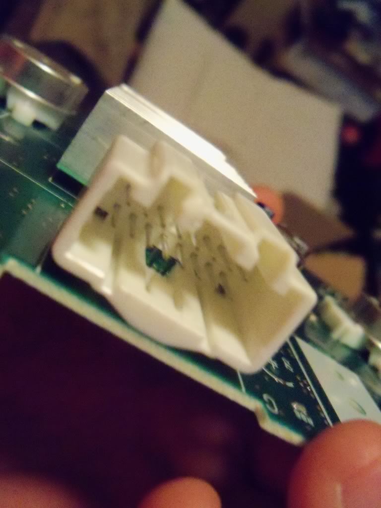
Or if someone could show a close up picture of their harnesses with the coloring clearly visible. Or just tell me the function of the pins in each of the 2 harnesses. I dont want to just go around with a 9-volt till I see something light up :P. Thanks again!
I am comfortable soldering and pin extracting and such and I am just looking for information on exactly which wires handle what. I will be using something called a revburner in order to get this functioning with my pc.
More info on Revburner: http://www.symprojects.com/shop/rev-burner/
Im looking to get the LEDs functioning along with the speedometer and tach and possibly a boost gauge done with the temp gauge on the cluster. Basically I just am looking for a pin out of the harnesses or how to wire directly to the board for overall power to the cluster and where the speed sensors are etc. If anyone can help me out on this project I would greatly appreciate it, if you require pics or more info to help me out I will gladly supply anything I can. Thank you!
SMKOUT333
EDIT:
Or if someone could show a close up picture of their harnesses with the coloring clearly visible. Or just tell me the function of the pins in each of the 2 harnesses. I dont want to just go around with a 9-volt till I see something light up :P. Thanks again!
Last edited by SMKOUT333; Mar 29, 2011 at 10:29 PM.

Registered User
Joined: Mar 2007
Posts: 915
From: Newark,ny
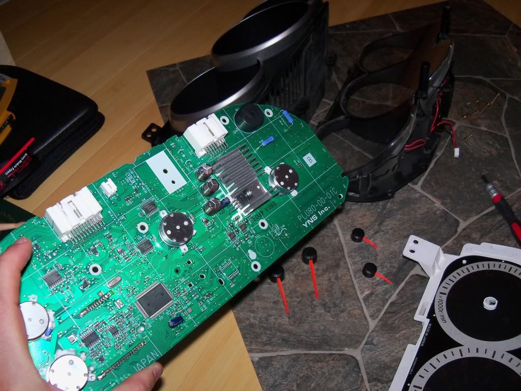
the speedo, tach, fuel gauge and all the lights are driven from the on board micro. So if you'd like to use them i'd say to just wire everything on your own, since many of the signals are over the CAN bus.
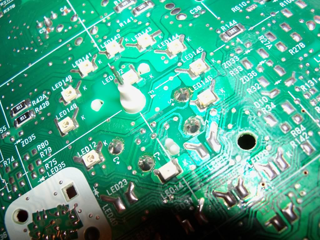
It looks like all the LED's are driven from a common 12V, diode protected from a common feed and each LED has its own resistor on the high side. The ground is switched on each with a transistor, so you can jumper across the 'negative' side of the LED to ground and not cause any issues.
Good luck, let me know if there are any other things you need help with - but they don't do much for documenting the individual connections, since at that point, it's not really car wiring, which is what the manual is for.

Thread
Thread Starter
Forum
Replies
Last Post
Currently Active Users Viewing This Thread: 1 (0 members and 1 guests)