PJB TNS issues. External fix possible?
 September-21st-2011, 06:47 PM
#16
Registered User

Join Date: Mar 2007
Location: Newark,ny
Posts: 913

The light switch is a switched 12V source on pin I on J-03 - black with a white stripe, so that should connect to 85 instead of connecting to the JP-03 pin AP.
Test that connection first, make sure it's a switched 12V source when the light switch is turned to the running lights position.
Test that connection first, make sure it's a switched 12V source when the light switch is turned to the running lights position.
 September-21st-2011, 07:14 PM
#17
Registered User
Thread Starter

Join Date: Sep 2011
Posts: 12
Sounds good. This is the last question I have before I attempt the fix. As it stands, when the TNS relay works (which becomes rarer every day), when I turn on my running lamps, my radio and and odometer display dim a little bit. I'm guessing that dimming will be gone with the external relay, correct?
September-21st-2011, 07:50 PM
#18
Registered User
Thread Starter
Join Date: Sep 2011
Posts: 12
Also, because I'm feeding the power back into the system, the wires should be soldered onto the burnt end of the fuse, not the side that was supplying or sending power through it before it was burnt, correct?
September-22nd-2011, 07:01 AM
#19
Registered User
Join Date: Mar 2007
Location: Newark,ny
Posts: 913
I'm not sure about the dimming, when everything is working properly the backlight of the instrument cluster should dim to the 'night' level for the lack of a better term. The radio should do the same, this level is controlled with the brightness adjustment on the dash to the left side of the steering column.
As for the 'burnt end of the fuse' - if you plug the fuse in backwards, it will just attach to the 12V source that should be from the TNS relay anyway, and not power the lights. So when each fuse is installed in the proper orientation, they will power the appropriate lighting system. No damage from having one in backwards, but you may need to switch a few around to get them in the right position. It is highly likely that one side of all the fuses is the source of power, and the other is the load - so all should end up with the wire on the same side of the fuse (I.E. to the right).
Good luck, let us know how it turns out.
 September-25th-2011, 09:40 PM
#22
Registered User
Thread Starter
Join Date: Sep 2011
Posts: 12
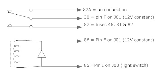
You rock! It worked! I just had to make one change. It didn’t work with terminal 85 connected to a ground and 86 to the light switch. It looks like the factory switch is a grounded switch. The only way I was able to get a 12 volt reading with my voltmeter was connecting the positive lead to a 12v source and the other to the light switch wire. So instead of connecting a ground to terminal 85, I connected the light switch wire. I connected terminal 86 to a 12v constant.
I still used a diode from 85 to 86, striped side towards the 12v constant (86). Also, the dimming (night mode) works fine but I had to leave the light switch wire intact and just tap into it. When I cut that wire completely, my dimmer wasn’t functional. I made a new diagram for what I did. Let me know if the setup in the diagram looks off.
Thanks again for all of your help! I appreciate the time you put into it and will be forever grateful!
September-26th-2011, 07:04 AM
#23
Registered User
Join Date: Mar 2007
Location: Newark,ny
Posts: 913
I am suprised the factory switch didn't match what was in the wiring diagram... then again, maybe I misread something.
In any case, glad to see it worked, and yes, the diagram looks fine. I'm happy to be a help.
In any case, glad to see it worked, and yes, the diagram looks fine. I'm happy to be a help.
December-16th-2013, 03:41 PM
#24
Registered User

Join Date: Oct 2013
Posts: 2
You rock! It worked! I just had to make one change. It didn�t work with terminal 85 connected to a ground and 86 to the light switch. It looks like the factory switch is a grounded switch. The only way I was able to get a 12 volt reading with my voltmeter was connecting the positive lead to a 12v source and the other to the light switch wire. So instead of connecting a ground to terminal 85, I connected the light switch wire. I connected terminal 86 to a 12v constant.
I still used a diode from 85 to 86, striped side towards the 12v constant (86). Also, the dimming (night mode) works fine but I had to leave the light switch wire intact and just tap into it. When I cut that wire completely, my dimmer wasn�t functional. I made a new diagram for what I did. Let me know if the setup in the diagram looks off.
Thanks again for all of your help! I appreciate the time you put into it and will be forever grateful!
December-17th-2013, 08:05 AM
#25
Registered User
Join Date: Mar 2007
Location: Newark,ny
Posts: 913
I have no photos, but I used a small "radio shack project box" type little plastic box with a circuit board & relay inside it just to keep it from bumping into things and strapped it to the wiring under the dash.
Did you use this type of fix? Or is the car otherwise stock and the lights are stuck on?
It's possible that the relay for the low beams went bad, though the bad part is that's on the control module in the car, not a replacable relay I don't think. You'd have to check near the battery, swap the relay for the lights with the horn for example. That would tell you if it's the relay or part of the control wiring.
December-19th-2013, 05:34 PM
#26
Registered User
Join Date: Oct 2013
Posts: 2
I expect problems with PJB :/
https://www.mazda3club.com/showthrea...t=52540&page=2
Do you know which relay under hood is responsible for low beams?
https://www.mazda3club.com/showthrea...t=52540&page=2
Do you know which relay under hood is responsible for low beams?
August-6th-2018, 04:39 AM
#27
Registered User

Join Date: Jul 2018
Posts: 2
Hi. I posted a lenghtly post as well as new thread on how to easily solve this issue with TNS that is becoming quite common and not easy to fix or expensive. But the post is avaiting admin/moderator approval. I would be glad if the solution would be publicaly available, so admins/mods can You please check this posts for approval?
October-12th-2018, 07:14 PM
#28
Registered User

Join Date: Oct 2018
Posts: 4
I know this is a very old thread but I wanted to say thanks for all this info. It is a bit confusing even for someone that claims to be very mechanically inclined, but I was able to make head and tails of it after thorough review. I am going to finish up my work tomorrow or sunday and post back what I did for clarity for future viewers. I basically did exactly what josephc04 did in his last diagram (post from september 25th 2011), but I had some issues that baffled me for a while...
I'll post more info later, but I had a lot of confusion just locating the correct wires in the correct harness connectors. It all makes sense now, but was confusing at first. Also, before cutting any wires I originally just skimmed insulation off the wires with a razor then used alligator clips to "test" everything before making permanent. I also pulled the 3 fuses. Everything worked perfect, so I figured it was easy as pie after that....wrong, lol. I cut the 3 wires to the tail lights, license plate lights, etc. and when I finished final wiring with heat shrink, etc. half the crap didn't work!!! Figured I had a bad connection, did a bunch of troubleshooting and came up empty handed. Finally I realised that I hooked to the wrong side of the cut wire on 2 of the 3 wires. I thought/assumed I had to hook to the wire going out to the car, not the module side. So I switched it and now the other half of the stuff worked, but the original stuff that worked didn't lol. I was getting frustrated now... I then realized that for 2 of the 3 wires you have to hook to BOTH sides, or just not cut it in the first place and just tap into them. I quit there, ran out of daylight, so will finish this weekend, but confirmed with gator clips how it needs to be wired.
Like I said I'll post more clear/in depth info later on. This really isn't hard to do at all, just hard to make sense of all the diagrams. I figure if I post something clarifying all that it might help some others as this thread helped me fix my issue, and for only a few bucks.
October-16th-2018, 07:03 PM
#29
Registered User
Join Date: Oct 2018
Posts: 4
Alright so here's a short write up of how I used the info in this thread to wire up my 2004 mazda 3. This is what I did to fix the interior dash/radio lights and tail lights not working (intermittently, but like 95% of the time). I didn't realize but the license plate light is also tied in with this.
I marked up some pictures that others posted to try to further clarify what is required, hopefully you can make out my bad hand writing. There's only like ~6 wire connections that need done, it's not very difficult.
1) Remove fuses F46, F81, & F82. This ensures the original circuits are disconnected and can't cause problems if they intermittently work properly. F46 is Front & Rear Parking Lights (RH side) and the License Plate Light, F81 is Front & Rear Parking Lights (LH side), and F82 is Interior Illumination.
2) The two connectors that you need access to are the large ones that plug into the top of the PJB (as it sits in the car). They are called J-01 & J-03 on the wiring diagram but on the PJB they are labeled "Front 1" (J-01) & "Cockpit 1" (J-03). This took me a while to figure out.
3) You will be cutting/tapping into the original fuse F46 wire (spot K on connector J-01), F81 wire (spot AC on connector J-01), & F82 wire (spot H on connector J-03). They are all O/L (Orange with Light Blue stripe). All the wires that you will be modifying need "tapped" into, not cut, except for one. This is what caused me so much trouble. The only one that I cut and wired into only one side (the side going out to the body, not to the PJB) was the F82 Interior Illumination wire. What I found on the F46 wire (Front & Rear Parking Lights (RH side) & License Plate Light) & F81 wire (Front & Rear Parking Lights (LH Side)) was that if you cut the wires, the side going to the PJB only gives power to the Front Parking Lights and the side going to the body of the car only gives power to the Rear Parking Lights and License Plate Light. In my opinion, this wasn't clear in the info in this thread (though, I don't claim to be an expert in this field)... Also, make sure to install a new fuse holder with 7.5 amp fuse on each of the three lines (F46, F81, & F82 wires). These fuses should be installed between the new external relay and where you make your wire taps/connections to the harness.
4) Use spot F on J-01 (Original Power in to TNS Relay) to power your new external relay (30 and 86).
5) Use spot I on J-03 (Light Switch Signal) to trigger your new external relay (85).
I hope this helps...This only cost me like ~$10 and worked perfectly. I haven't found anything electronically in the car that doesn't work, so I don't think that one wire that I cut instead of tapping into (for the Interior Illumination) does anything going into the PJB. But, being that the fuse was removed you should be able to simply tap into it. Hind sight is 20/20 and looking back I would have just tapped into all the wires to make it so much easier and save a ton of hassle/troubleshooting. With clear details, you should be able to complete this whole job in under 2 hours pretty easy using simple crimp/heat shrink connectors.
I'm having trouble posting the images....I may have to come back to post them later...

